

Basic Electronic Component Symbols that Every PCB Design Engineer Should Know
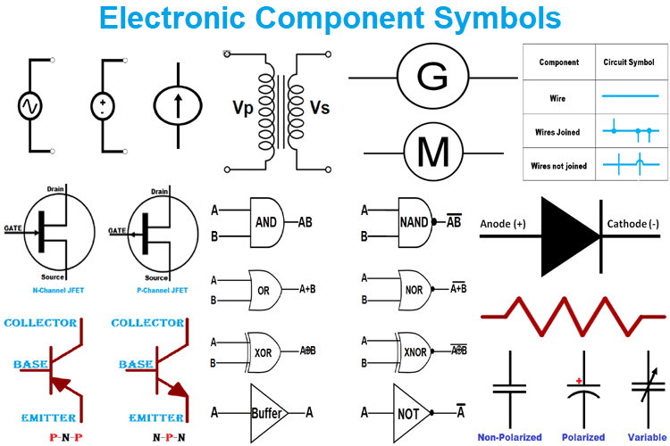
The process of designing a PCB starts from understanding the circuit schematics and proceed with converting the schematics into a PCB Layout. To understand the schematics, any designer needs to know the circuit symbols for all basic components. If you are a beginner who is just getting started, then this article will help you to understand all the basic component symbols that you will find on a circuit diagram. You can also check out the Introduction to PCB article to understand the basics of PCB Design.
Wires and Jumpers
In an Electronic Circuit, Wires are represented as plain straight lines. These straight lines are used to connect one component with another component in the circuit. The common type of wire symbol is shown below.
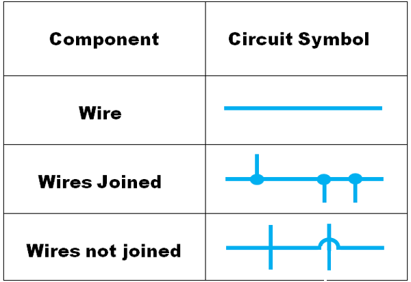
Sometimes the wires in the circuits are connected with one another, and sometimes the wires are taken across the other wires without getting connected. In a circuit diagram, the wires that are connected are represented in the form of a dot, whereas the non-connected wires that are jumping over the other wire are represented without any dots or by a small curve.
Power Sources
There are a variety of devices that one can use as a power source for his/her electronic device and circuit. Each power source is different from one another and they are represented by different symbols.
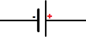
Cell:
A cell is one of the most commonly used power sources that can deliver a minimum power to a circuit. The symbol of the cell is given by a short line and a long line separated by a small gap. The symbol tells about the two electrodes used in the cell, the long line represents the positive electrode/terminal, whereas the short line represents the negative electrode/terminal.
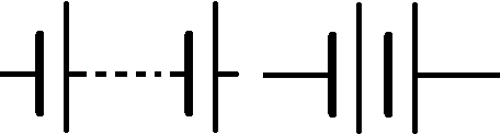
Battery:
When more than one cell is connected, it is called a battery. Batteries are multiple cells connected to each other. Hence the symbol of the battery is also given as more than one cell attached to another cell. Sometimes more than one cell is connected by an external element to form a battery, the connected form of the battery is represented by two cells connected with dotted lines.
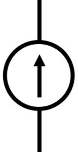
Current Source:
The Current Sources are used in the circuits that require constant current flow even when there are variations in the voltage. The Symbol of the current source is given as a circle with an arrow inside that represents the direction of the current flow.
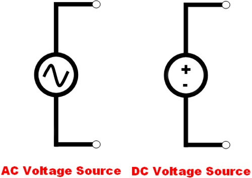
Voltage Source:
The voltage sources are used in a circuit that requires a constant voltage for its operation even if there is a change in resistance and the output current. There are two types of voltage sources, an AC voltage source and a DC voltage source, the symbol of an AC voltage source is given by a circle with a sinusoidal wave inside, and the symbol of the DC voltage source is given by a circle with a plus and a minus sign inside.
Passive Electronic Components
The basic electronic components include three devices, namely, Resistor, Capacitor, and Inductor. These three are the common components that are used in all the circuits, in other words, it is hard to create a circuit or build an electronic device without resistance, inductance, and capacitance.
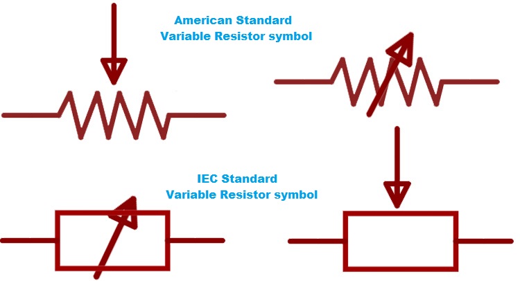
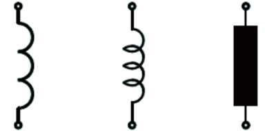
Resistors:
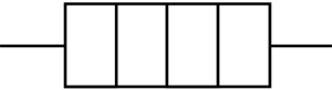
The resistor is a piece of wire that is wound on a ceramic or metalcore, this dense piece of wire will block the flow of current. The symbol of the Resistor is given by a zig-zag line with two ends as the wounded wires will be forming zig-zag lines. According to IEC standards, the symbol of a resistor is given by a simple rectangle

The symbol of the variable resistor is given with an arrow mark across or above the symbol of the constant resistor. The arrow indicates the adjustable wiper that is used to control the resistance.
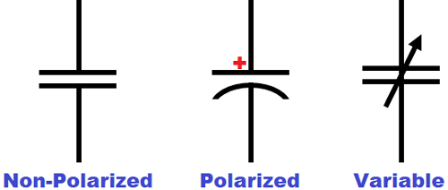
Capacitor:
Capacitors are mainly used in a circuit to store energy and dissipate it when required. There are two types of capacitor, polarized and non-polarized capacitors. The polarized capacitors are simply given by two parallel lines, they do not have any polarity, hence they can be connected on both sides. The polarized capacitor is denoted with a plus symbol on the positive terminal (Anode) of the capacitor, whereas the negative terminal (Cathode) of the polarized capacitor is represented as an arc instead of a line.
Apart from these two, there is a third type of capacitor, which is the variable capacitor, the symbol of the variable capacitor is similar to the non-polarized capacitor but it has an arrow on it. Symbol of Electrolytic capacitor and the symbols of Ceramic capacitor is also shown below marked as Polarized and Non-polarized capacitor respectively.
Inductor:
Inductors are mostly used to generate magnetic fields, in other words, an inductor stores the energy in the form of the magnetic field. The inductors are used as filters, sensors, and storage units in the electronic circuits. An inductor is simply a piece of wire wound on a straight or ring-shaped core, hence the symbol of the inductor is given as a wounded wire or as curved lines. According to the international standard, an inductor is given as a shaded rectangular box.
Symbol of Different Types of Diodes
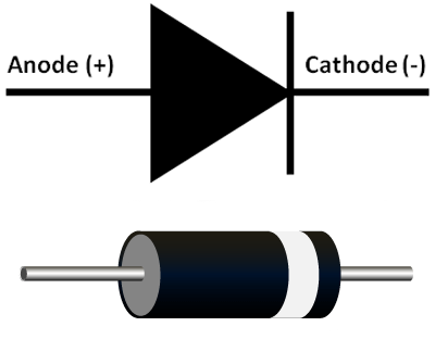
Diodes:
A Diode is a semiconductor device that allows the flow of electric current in one direction (Forward Direction) and opposes it in the other direction (Reverse Direction). The symbol of the diode is given by a triangle with a short line on one of its vertex, the triangular structure will represent the direction of the current flow. The side with the base of the triangle acts as the Anode (positive terminal), whereas the side with the short line represents the cathode (negative terminal).
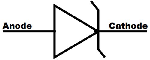
Zener Diode:
The Zener Diode is similar to a normal diode, but it has the ability to allow the current in the reverse direction when the applied voltage goes beyond the breakdown voltage. The image below shows the symbol of the Zener Diode, you might be able to notice that the straight line of the normal diode is replaced with an extended ‘Z’ in the Zener Diode.
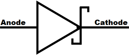
Schottky Diode:
The Schottky diodes have a low forward voltage drop and used in applications that required fast switching. The symbol of the Schottky diode is given below.
LED (Light Emitting Diode):
Light Emitting Diode is one of the optoelectronic devices that can dissipate visible light when it is connected to the power source. The LEDs can emit light in different colors such as orange, yellow, blue, green, and white. The Symbol of LED is similar to that of a normal diode but it has two arrows that represent the emission of light.
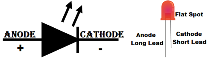
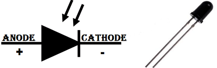
Photo Diode:
Photo Diodes are the device that converts photons from the light into electrical current or voltage. The symbol of the photodiode will be similar to the LED, the only difference is that the arrows are pointed towards the Diode, which represents the light falling on the diode.
Transistors
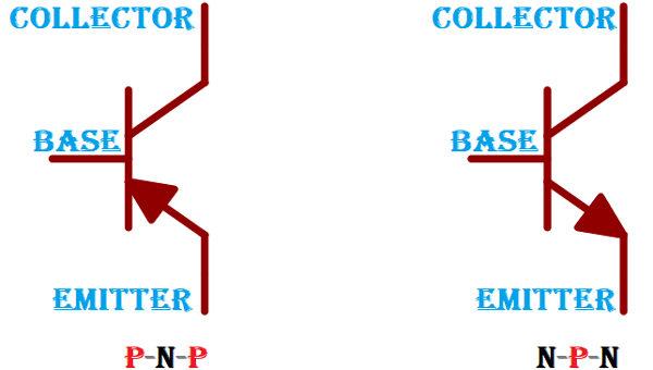
BJT (Bipolar Junction Transistor):
The BJT is a three-terminal device that can be used as a switch or as an amplifier, there are two types of BJTs, namely, NPN transistor and PNP transistor, both the symbols are given below. In the symbol of PNP transistor, the arrow in the emitter will be directed towards the base, whereas in the symbol of NPN transistor, the arrow in the emitter is directed away from the base.
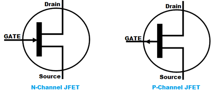
JFET (Junction Field Effect Transistors):
The Junction Field Effect Transistors are the three-terminal switching devices in which the flow of current is controlled by the voltage applied to the gate terminal. There are two types of JFETs, the N-Channel JFETS and P-Channel JFETs. Both, the symbol of N-Channel JFET and the symbol of P-Channel JFET are shown below.
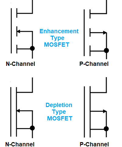
MOSFET (Metal Oxide Field Effect Transistor):
The MOSFET can be used as a switch and amplifier. Depending on the type and mode of operation, the MOSFET is classified into four types, namely, N-Channel Enhancement type, P-Channel Enhancement Type, N-channel Depletion type, and P-channel Depletion type. All the symbols of MOSFET are illustrated by different figures as given below.
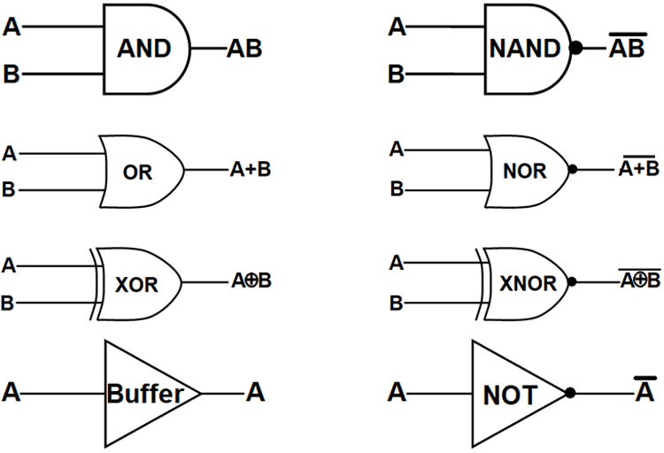
Logic Gates:
Logic gates are used to implement Boolean functions in a circuit. They are used to deliver single output by combining two or more inputs. There are four basic logic gates, namely, AND, OR, NOT, and XOR, when the output of these gates is negated or inverted, they will form the logic gates such as NAND, NOT, and XNOR.
For better understanding, consider the input/output high is 1, whereas low is 0 and use them in the formulas of the logic gates.
AND: The AND gate works on the logic Y=A.B, the output will be high if both the inputs are high.
OR: The OR gate works on the logic Y=A+B, The output will be high if any one of the inputs is high.
NOT: NOT gate will have only one input, the output will be the inverted form of the input, that is, the output will be high if the input is low and vice versa.
NAND: NAND gate is the combination of NOT and AND gate. The output will be low if both the inputs are high, otherwise, the output will be high.
NOR: NOR gate is the combination of NOT and OR gate. The Output will be high if both the inputs are low, otherwise, the output will be low.
XOR: XOR stands for Exclusive OR gate, here the output will be high only if any one of the input is high, otherwise, the output will be low.
XNOR: XNOR stands for Exclusive-NOR gate, here the output will be high only if both the inputs are high or both the inputs are low.
Input/Output Devices
The Input/Output devices are the components that can be used to give input and get output from a circuit in the form of light, sound, and heat.
Microphone:
A Microphone (MIC) is a form of a transducer that is used to give input to the circuit in the form of sound, a microphone can convert sound energy into electrical energy. The symbol of the microphone is shown below.
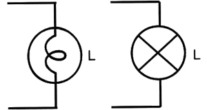
Bulb:
The Bulb is used to show the output in the form of light and its symbol is given by a circle with an X mark in it or by a circle with a single loop inside.
Heater:
A Heater is a form of a transducer that converts electrical energy into heat energy and it is given by a rectangle with three lines inside.
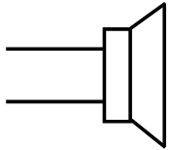
Loudspeaker
The Loudspeaker is an output device that is used to convert electrical energy into sound energy. The symbol of the speaker will look like the image below.
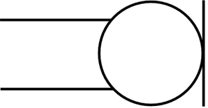
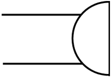
Buzzer:
The Buzzer can be used as an alarming device in the electronic device and it will give a constant buzzing sound when it is electrified. The buzzer symbol is given by a semicircle with two terminals.
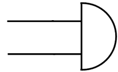
Bell:
The bell and the buzzer have a similar function and almost a similar symbol, the symbol of a bell will be the inverted form of the buzzer.
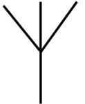
Aerial:
An Aerial is used to represent a transmitter or a receiver in an electronic circuit. The symbol of the aerial will look like the footprint of a bird.
Protection Devices
No matter a circuit is simple or complex, we need to use some sort of protection device in the circuit to protect the equipment from short circuit, over current and over-voltage conditions. The following are the symbols of some common protection devices used in circuits.
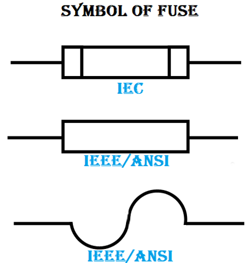
Fuse:
A fuse is a simple protection device that is used in almost all the circuits. The fuse breaks the circuit when there is a high current flow in the circuit. The symbol of a fuse is given by a simple rectangle or a sinusoidal wave with two terminals.
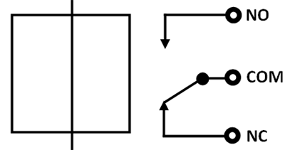
Relay:
A relay can be used to close or open a circuit when a magnetic field is applied to the coil in the relay. Relays are mainly used to isolate one part of the circuit from another part. The Relay in a circuit is given by the following symbol.
Electromagnetic Devices
The most commonly used electromagnetic devices include a generator, motor, and transformer.
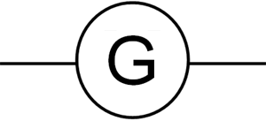
Generator:
The Generator is an electromagnetic device that converts rotating motion into electrical energy. The symbol of the generator is given as a circle with the letter G in it.
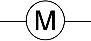
Motor:
A motor is an inverse of a generator, The motor converts the Electrical energy into rotating motion and the symbol of the motor is given as a circle with the letter M in it.
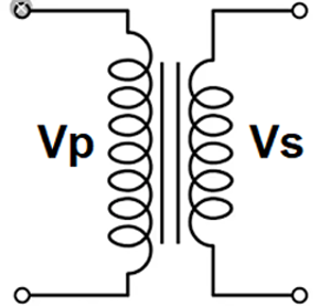
Transformer:
A transformer is an electromagnetic device that is used to step up or step down the voltage or current without changing the frequency of the power. The symbol of the transformer is represented by two coils kept aside from one another. The coil on the input side of the transformer is called the primary winding whereas the coil on the output side of the transformer is called the secondary winding.
The Above article has given you the knowledge about the symbols of almost all the different electronic components used to build a proper circuit. Remembering these symbols will help you to read and understand an electronic circuit whenever you see one.

Latest Articles
-

Single-Sided vs. Double-Sided PCBs: Which One Is Right for Your Project?
-

Exploring the Different Types of PCB Layers and its Purpose
-

PCB Connectors: A Comprehensive Guide to the Different Types and Their Applications
-

PCB Soldering Steps
-

Basic Electronic Component Symbols that Every PCB Design Engineer Should Know
-

Home Made PCBs – A Step by Step guide to build PCBs in your Home
Comments