

Eagle Tutorial 4/4 – Creating new schematic symbols and custom footprints in EAGLE CAD
The best part of the EAGLE is its wide collection of component libraries. During our previous EAGLE PCB tutorial, we have learned how to create schematics and how to create a board layout in EAGLE. In most of the case, you will find all the components which you need to make circuits. But in some cases, you cannot find the component from the library or whatever component you need might not be available in a standard format. Now, what to do in this condition? EAGLE has the answer to your question. HOW? Let’s do this in brief.
Creating a new component in the EAGLE is not an easy task. Before making a component, you must have all the information about that component. These details are easily available from the datasheet of the component you are using. The datasheet of the component is the most important part of any project but it is very tedious to read. In EAGLE, components are stored in the library. If you want to make your own library for a specific part, you need to have three things, symbols, devices, and packages. This all things together make a library.
Device: You will have one or more than one part of the same device library. These parts contain a schematic symbol and a package.
Symbols: You will have a symbol, which gives a visual representation of a part. When you use this part in the schematic diagram, it looks like this symbol.
Package: You will have a package for every device, which gives an actual representation of the part. In the board layout, this part looks like this package.
This is how libraries are organized in the EAGLE. Now, you understand how the library works. Let’s create a library folder.
- From the control panel, click File > New > Library.
- It will open in a new library window. Save library by File > Save or (ctrl + S).
- Give the name of the library and it will save in .lbr format. I have given the “First-Library” name.
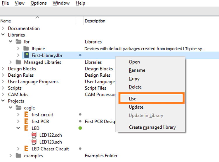
- Now, you have to activate this library. Control panel > libraries > Right-click on the name > use. Now, it shows a green dot next to the name of your library.
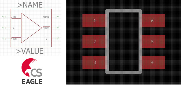
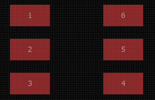
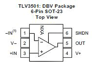
TLV3501 is a comparator. This package is not available in the EAGLE library. We will create this part in the EAGLE. First, you have to download the datasheet of TLV3501A-Q1. Don’t worry. You do not need to read all the things in the datasheet. We are going to design a device TLV3501AIDBVR. This device has 6 pins. For this device, page number 23 to 27 of the datasheet is import for us.
There are six pads as shown in the figure. We will give numbers according to this figure.
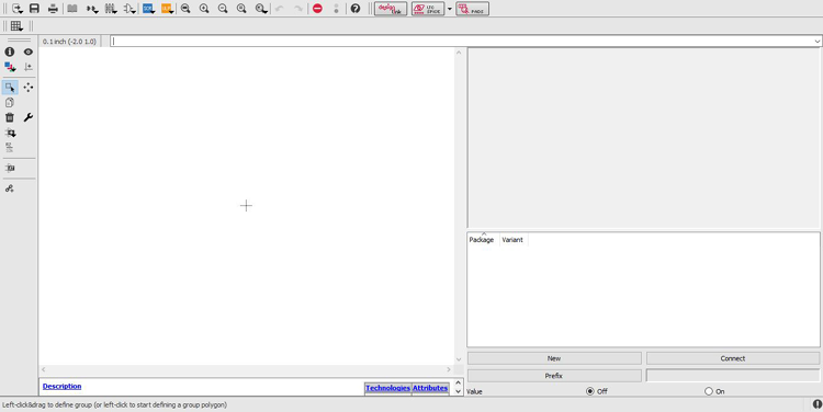
We have already created a library. In this library, we want to add this device. Now, to open this library, right-click on the name > open. It will open in a new window. It looks like the below screenshot.
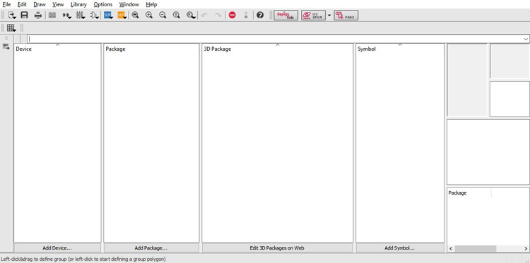
This screen is divided into four parts;
- Device
- Package
- 3D Package
We have discussed these parts at the starting of this blog. Now first we want to add a package of the device.
Create custom footprint on EAGLE
Step-1 To create a package, click on “Add Package”. It will ask the name of the package and open a schematic window.
Step-2 First thing you need to change the size of the grid. For that, click on the GRID icon. ![]() Change the size of Grid, from inch to mm and value is 0.05. When you set this grid setting, you cannot see the grid. Zoom in the screen by mouse roller or use the Zoom In icon.
Change the size of Grid, from inch to mm and value is 0.05. When you set this grid setting, you cannot see the grid. Zoom in the screen by mouse roller or use the Zoom In icon.![]() Now, it is visible.
Now, it is visible.
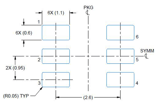
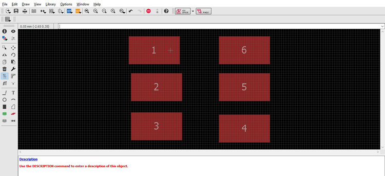
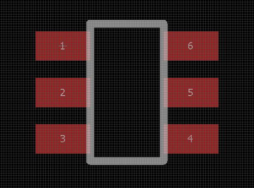
Step-3 From the above figure and datasheet, we can find the size of all pad. There are six pads in this device. The dimension of the pad is 1.1mm X 0.6mm. Click on the SMD icon to add a pad. ![]() Add 6 pads. Change the size of the pad from the SIZE tool.
Add 6 pads. Change the size of the pad from the SIZE tool.
Step-4 Pad Pitch is the distance between two pads (center to center) with the reference of the X-axis and Y-axis. Here, the X-axis pitch of 2.6mm and Y-axis pitch of 0.95mm.
Step-5 Rename pad. Click on the NAME icon ![]() We will set the pad number according to the datasheet.
We will set the pad number according to the datasheet.
Step-6 Placing the pad.
We will set a pad pitch with the help of the grid. We have a set grid of 0.05mm. You can see the cursor position Start from the origin point.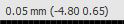 We want to place 6 pads. Now, place pad-1 at the origin. Select MOVE > ctrl + left-click on the pad-1.
 In this way, the cursor selects pad-1 from the center of the pad. Now move the cursor to (0.00 0.00). Place all pads as shown below dimension.
Pad-1: (0.00 0.00)
Pad-2: (0.00 -0.95)
Pad-3: (0.00 -1.90)
Pad-4: (2.60 -1.90)
Pad-5: (2.60 -0.95)
Pad-6: (2.60 0.00)
Now, all pads are placed as shown in the datasheet.
Step-7 Add physical dimension
Find the physical dimension of the device from the datasheet. This is available on page no 23.
Create lines of a given dimension. Let find the dimensions for lines. These lines are placed in the 51 (tDocu) layer. For that click on the layer and select 51 layer.
Line-1: (2.05 0.45) to (0.55 0.45)
Line-2: (0.55 0.45) to (0.55 -2.35)
Line-3: (0.55 -2.35) to (2.05 -2.35)
Line-4: (2.05 -2.35) to again (2.05 0.45)
Step-8 Add name and value.
Select the TEXT icon from the toolbar (left side of the window).![]() Select layer 25 (tName). Enter “>NAME” in the text field. Select the size according to the design. Same way enter name “>VALUE”. Press ESC to exit from the text.
Select layer 25 (tName). Enter “>NAME” in the text field. Select the size according to the design. Same way enter name “>VALUE”. Press ESC to exit from the text.
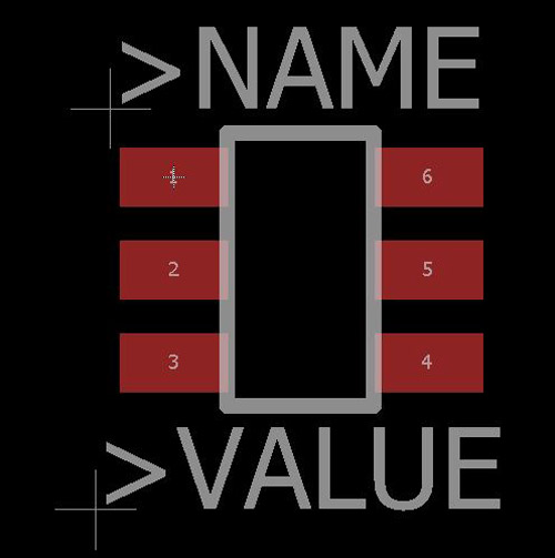
DONE!! You have created the package of this device. Now, we will make a symbol.
Creating schematic symbol on EAGLE
The pin configuration of TLV3501 is given on page number 3 of the datasheet. To create the symbol, go to control panel > library > right-click on the name of your library > open. The library window will open. Here you can see the package is available which we have already done. Now, we are going to make a symbol.
Before starting to make a symbol, we must know about pin configurations. As we know, there are six pins in this device. Pin description is given in the datasheet.
|
Name |
Pin Number |
Description |
|
-IN |
1 |
Negative Input (inverting input) |
|
+IN |
3 |
Positive Input (noninverting input) |
|
OUT |
5 |
Output |
|
SHDN |
6 |
Shutdown (the device is ideal when this pin is not in use) |
|
V- |
2 |
Negative (lowest) power supply |
|
V+ |
4 |
Positive (highest) power supply |
Step-1 Select Symbol
Select Symbol from the toolbar. ![]() Give a name to the symbol. OK to confirm the name.
Give a name to the symbol. OK to confirm the name.
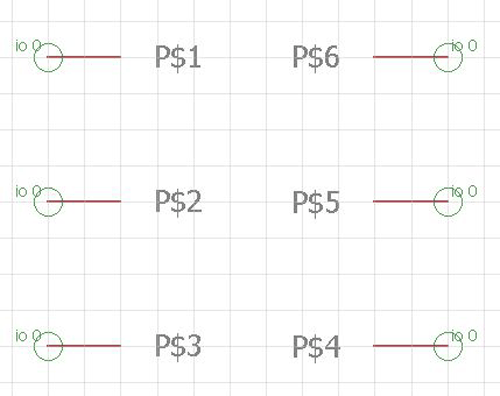
Step-2 ADD Pin.
A symbol Editor window will open. Add Pins as per the datasheet. Select the Pin icon. ![]() ADD 6 pins. Use right-click twice to rotate the pin 180®.
ADD 6 pins. Use right-click twice to rotate the pin 180®.
Step-3 Rename Pin.
Select the Name icon.![]() Select pin and give name as per the datasheet.
Select pin and give name as per the datasheet.
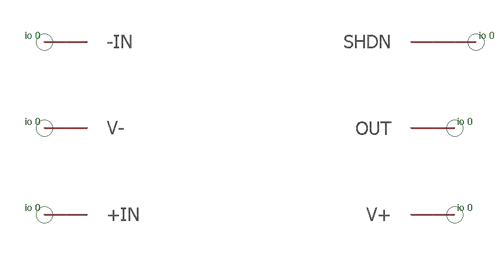
Pin-1: -IN
Pin-2: V-
Pin-3: +IN
Pin-4: V+
Pin-5: OUT
Pin-6: SHDN
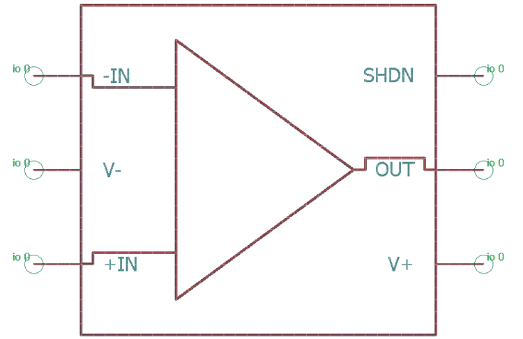
Step-4 Add symbol lines.
Select the Lines icon. ![]() Draw the line as per given in the symbol. Use left mouse click to start the line. You can delete a line by using a delete key or delete icon. Use ESC to end the line. Use the below toolbar to format the line.
Draw the line as per given in the symbol. Use left mouse click to start the line. You can delete a line by using a delete key or delete icon. Use ESC to end the line. Use the below toolbar to format the line.

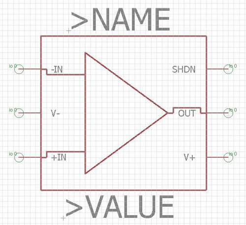
Step-5 Add Name and Value.
Select the Text icon. ![]() Before adding text change the layer. To change the layer, click on the layer icon and choose layer 95 NAME. Add Text >NAME and >VALUE. Use the Text toolbar to format the text.
Before adding text change the layer. To change the layer, click on the layer icon and choose layer 95 NAME. Add Text >NAME and >VALUE. Use the Text toolbar to format the text.
Step-6 Change the length of Pin (Optional)
The length of the pin is not the same for all symbols. In this case, the size of all pin is the same. But in case if you need to change the length of the pin,
right-click on pin > Properties > length.
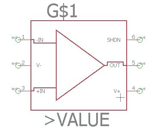
In this example, the length of all pin is the same. Just for understanding, we have made this difference.
THAT’S IT!! You have created the package and symbol both.
Now, we have to connect the package and symbol to complete this device. This is the last stage of creating part of the library.
Step-1 Open library
Open control panel > right-click on your library > open
Step-2 Add Device
Click on the “Add Device” or click on the icon of “Device”. ![]() Give the name to the device. It will open in a new window.
Give the name to the device. It will open in a new window.
Step-3 Add symbol
Click on the Add icon. ![]()
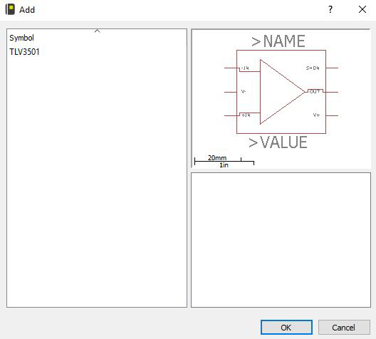
Here you can find the symbol. Select the name of the symbol and click OK.
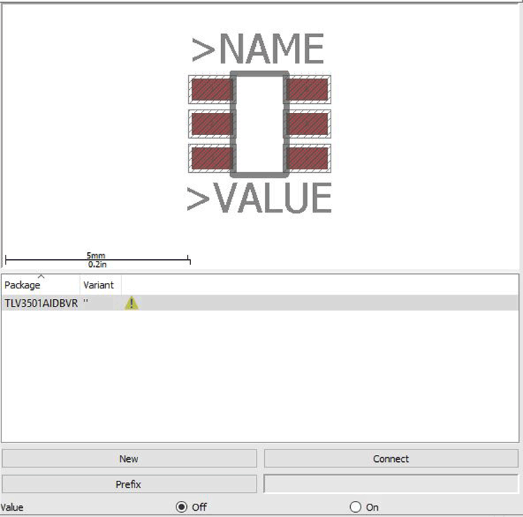
Step-4 Add package.
Click New (right-bottom corner) to add the package. Here you can find the package. Click on the name of the package and press OK. Now, you have added the symbol and package. But both are a different segment. We have to connect the package and symbol. When symbols and packages are not connected, a warning symbol displays at the right-bottom corner.
Step-5 Connect package with a symbol.
Click on the connect button on the left-bottom corner. A new dialog box will open. Here we will connect the pin with the pad. The pin and pad connect as per the datasheet.
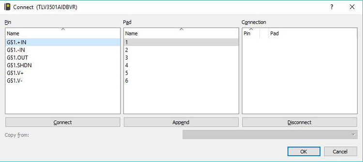
This dialog box divides into three parts. Pin, Pad and connection. First select pin and pad at which it is placed. The first pin is +IN and it is connected with the PAD-3. So, select pin +IN, then select pad3 and press connect. This connection appears in the last column. In this way connect all pin with a pad.
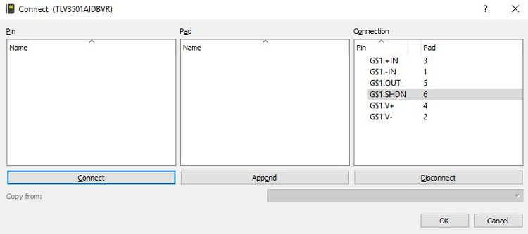
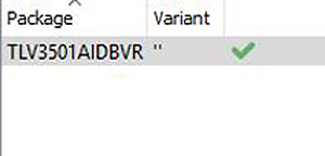
After connection all pins with pads, the warning shows before that convert into a green right symbol.
Step-6 Optional
Add a description: If you want to add a description of the device, you can add from the left-bottom corner.
Prefix: You can add a prefix, which shows the symbol of the device.
Enabling value: By default, this option is selected OFF. If you turn this ON, it allows adding the value at > VALUE. If this open is OFF, you are not allowed to change the >VALUE.

Latest Articles
-

Single-Sided vs. Double-Sided PCBs: Which One Is Right for Your Project?
-

Exploring the Different Types of PCB Layers and its Purpose
-

PCB Connectors: A Comprehensive Guide to the Different Types and Their Applications
-

PCB Soldering Steps
-

Basic Electronic Component Symbols that Every PCB Design Engineer Should Know
-

Home Made PCBs – A Step by Step guide to build PCBs in your Home
Comments