

Eagle Tutorial 2/4 - Drawing schematics in EAGLE PCB Design Software
In the first part of our eagle tutorial, we have learned about the Basics of PCB and Overview of EAGLE CAD software. Here to continue with our Eagle PCB tutorial, we learn to create a schematic diagram in EAGLE. To draw a schematic, we have chosen an LED chaser circuit. To know more about the circuit and how it works you can check this LED chaser tutorial, in this article we will not be concentrating on how the circuit works but only on how to design a PCB for this circuit.
Creating schematics on EAGLE:
Let’s start to create schematics and draw a simple EAGLE circuit diagram. Follow the below steps to make a schematic design.
Step-1
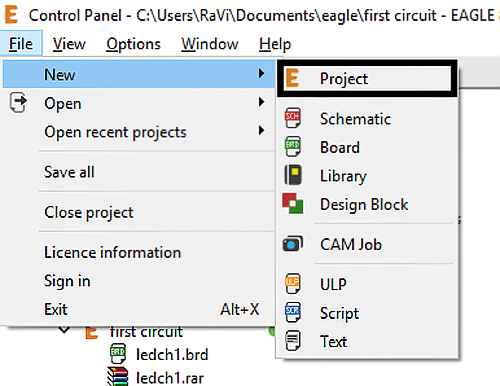
Open EAGLE. File > New > Project. Give a name for the new project.
Step-2
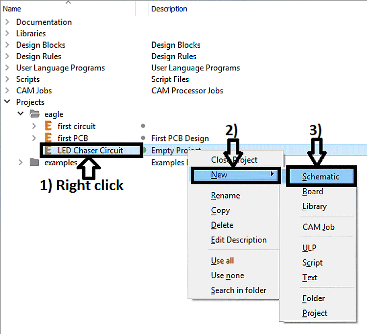
Give any name to New Project. Here, I have given “LED Chaser Circuit”. Now to create new schematic, right-click on the name of project > New > Schematic. The blank schematic will open in a new window.
Step-3
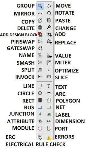
In this new window, the drawing tools are available on the left side. These icons (tools) are very useful to make a schematic.
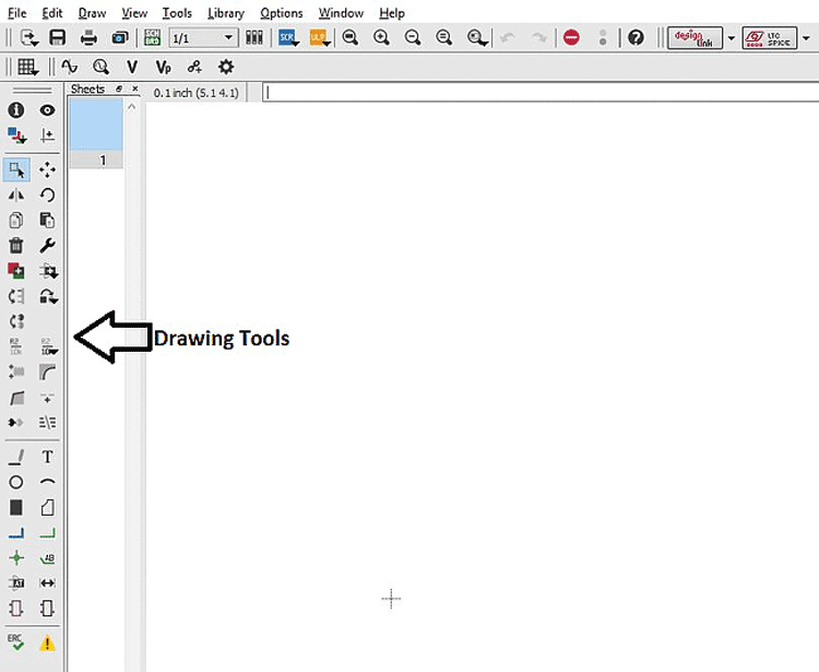
The drawing tools along with their names are shown below
Step-4
Enlist the components you need to make a circuit. In the previous tutorial, the LED chaser circuit is explained briefly. So, here we will not discuss this again. As shown in the circuit diagram of the LED chaser circuit, we need below-enlisted components. These components are added from the library. In the library of EAGLE, most components are available. To add a component in the schematic, use the ADD button from the design tool or you give ADD command in the command bar.
In the library, a search bar is available to search the component. For good search results, use ‘*’ before or/and after the keyword.
| Sr. No. | Name of Component | Path in Library | Component Description | Number of Components |
| 1 | Battery | Battery>AB9V | 9V BATTERY CLIP | 1 |
| 2 | 555 Timer | Linear>LM555N | DIL08 | 1 |
| 3 | Capacitor C2 - 10nF | rcl>C-EU>C-EUC0603 | C0603 | 1 |
| 4 | Capacitor C1 - 10uF | rcl>CPOL-EU>CPOL-EUE2.5-7 | E2,5-7 | 1 |
| 5 | POTENTIOMETER-VR | pot>TRIM_EU>TRIM_EU-PT10 | PT-10 | 1 |
| 6 | Resistor | rcl>R-EU>R-EU_0207/10 | 0207/10 | 12 |
| 7 | IC 4017 Counter | 40XX>4017>4017N | DIL16 | 1 |
| 8 | LED | led>LED>LED5MM | LED5MM | 11 |
STEP-5
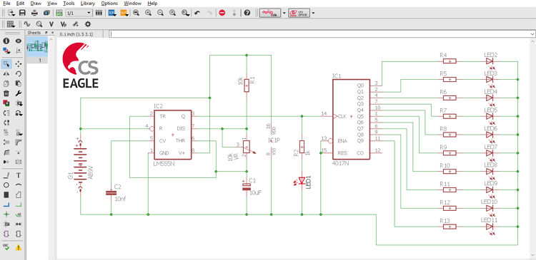
Add all these components in the schematic window. Now, connect all these components with a net. Net is available in the design tool. A final schematic will look like the below screenshot.
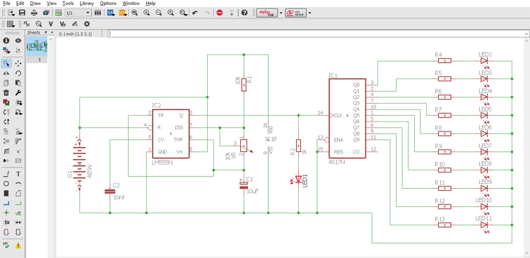
Connect all components properly with net and schematic is ready. This schematic is used to make a board diagram. We will discuss how to make a board diagram in the next tutorial.
EAGLE Schematics Drawing Tips:
- If you want to move any component, select MOVE from the drawing tool. To move the component in the group, select components, hold ctrl + click right to move.
- If you need to delete a component, select DELETE and use the left click on the component.
- Use the NAME button to give the name of the component. i.e. C1, C2 etc.
- Use the VALUE button to give value for a component. i.e. In this example, the value of capacitor C1 = 10uF.
- Copy/ paste is also available in the schematic.
After the complete circuit diagram, click on ERC. This tool is the best part of this software. ERC means Electrical Rule Check. This tool will check the diagram and find ERRORS and WARNINGS. When you click on this button, a new window will open and shows errors and warnings.

Latest Articles
-

Single-Sided vs. Double-Sided PCBs: Which One Is Right for Your Project?
-

Exploring the Different Types of PCB Layers and its Purpose
-

PCB Connectors: A Comprehensive Guide to the Different Types and Their Applications
-

PCB Soldering Steps
-

Basic Electronic Component Symbols that Every PCB Design Engineer Should Know
-

Home Made PCBs – A Step by Step guide to build PCBs in your Home
Comments