

Tutorial 1/4 - Getting Started with EAGLE for PCB Designing
Before the invention of PCBs, components were connected manually through the process of point to point wiring. For larger circuits, a greater number of components were used and it became very complicated and a tedious process to connect all component with a point to point wiring. Today as we know Printed circuit boards (PCBs) are used to form the connection between multiple components and also to provide mechanical support for these components. It is with the help of these PCBs we are able to build complex circuits in a smaller form factor. Hence is important for every engineer to learn PCB designing to design their own PCB boards for their circuits and applications.
Hence, in this sequence of articles we will learn how to design PCB boards with Eagle Software. This is a four part series, and in this first part we will brush up on our understanding of PCB and then learn about the Eagle CAD software, finally we will get it installed in our computer to be used in upcoming parts of this tutorial. If you are a beginner to the world of PCBs then is it highly recommended to read the Basics of Printed Circuit Boards article to understand the stuff discussed in this tutorial series.
Terminologies related with PCB designing
The first step to learn PCB designing is to get familiar with the terminologies that are commonly used when designing a PCB. The most frequently used terms are explained below, there are still a lot left but we will cover them as we move forward with our tutorial
Solder mask: It is a layer on top of the copper layer. Generally, this layer is green or red color. This layer is used to insulate the copper layer and helps the user to solder the component on correct places.
Silkscreen: On the top of the solder mask layer, white silkscreen layer is applied. This layer adds letters, numbers, and symbols of component for better understating of PCB. Generally, the silkscreen is in white, black, gray or yellow color. Most commonly, white color is used.
DRC: DRC stands for Design Rule Check. DRC is used to check our PCB design and to make sure the design does not contain errors such as traces that incorrectly touch.
Trace: A continuous path of copper on a circuit board is known as Trace. This path connects the lead of one component with another component. You can think of it as the PCB equivalent for wire.
Jumper: It is a wire to connect two pins or pads together. Less number of jumpers makes the design less complicated.
Pad: It is a piece of copper. The pins of the component are mechanically supported and soldered on the pads. Pads are normally silver in color and mostly in the shape of circle, oval or square.
Which PCB Designing Software should you learn?
There are many PCB designing software available in the market. You have to choose the software according to your budget, application, and knowledge. Here I have listed the most popular PCB designing tools; Eagle, Altium designer, Kicad, OrCAD, EasyEda, PADS, PCBworks, circuitmaker, etc.
As a personnel suggestion, I would say that the most commonly used and affordable software is EAGLE. For students and educators, Eagle has a free version and it also provides a lot of documents for learning PCB design thus making it beginner friendly. But of course you can read this PCB design software comparison article to decide on the software that would best suit you. You can also check out our tutorial series on different PCB software below
- KiCAD PCB Design Tutorials
- Eagle PCB Design Tutorials
- Altium PCB Design Tutorial
- OrCAD PCB Design Tutorial
- Proteus PCB Design Tutorial
- Fritzing PCB Design Tutorial
In this tutorial let’s get more familiar with EAGLE. It is available for free and here we discuss a free version of EAGLE. It works on Windows, MAC and Linux OS. So, from where to download? How to install? How to use? This all question you may arise and, in this article, I will try to answer all of your questions.
Introduction of EAGLE
EAGLE is a sort form of Easily Applicable Graphical Layout Editor. EAGLE CAD is developed by a German company CadSoft Computer. In 2016, EAGLE was acquired by Autodesk Inc. It is supported for Windows, Linux, MAC, and DOS.
There are three different types of Eagle Software, the three versions are
- EAGLE Free
- EAGLE Standard
- EAGLE Premium
The difference between all the three versions is tabulated below, for you to help with deciding the right package sutiable for your needs.
|
|
EAGLE Free |
EAGLE Standard |
EAGLE Premium |
|
Price for subscription |
Free |
$ 100 / Year |
$ 520 / Year |
|
Use for |
Hobbyist, students and learning PCB designing and electronics |
Product design and basic electronic |
Advance multilayer and complicated product designing and production level products |
|
Board area |
80 cm2 (12.4in2) |
160 cm2 (24.8in2) |
Unlimited Board area |
|
Schematic Sheets |
2 |
99 |
999 |
|
PCB layout |
Single-sided and double-sided PCB |
Multilayer PCB |
Complex multilayer PCB |
|
Library |
Library content access |
Building and managing library content (individual) |
Building and managing library content (team) |
Download and install EAGLE Software
As you would have noticed in the above table, EAGLE has a free version that is available for download from Autodesk website. The official download link is given below
Download EagleCAD 9.4.2 Software – Free Version
At the time of writing this article, the latest version of software is 9.4.2, but you can also download latest software that is available at your time. Since most of the basic features will still remain the same, you can still follow the same tutorial. The link given will take you to a page where you have downloaded the suitable software based on your Operating system.
Download the software and install it by following simple on-screen instructions. After installation, launch the software and you will be greeted with the dialog box below.
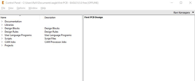
At top of control panel, the menu bar is available. It has File, View, Options, Window and Help. After that, you can see that, screen is divided in to two parts. Right side of the control panel is blank as shown in above screenshot. In this blank space, preview of PCB or block displays will appear as we begin using the software. The left side of the window consists of some important directories that will be useful for beginner , these topics are explained below
Documentation: Here you will get PDFs and manuals for help and support.
Library: In library, all components are available which we can use to design a PCB. In this component library, all frequently used components are avalabile. Each component will have its component symbol and component footprint. If the compoent you are using that is not available in this library, in this case, you can develop your own library with its own symbol and footprint. We will learn how to do that later in this series of tutorial.
Design block: In this tab, you can find some predesigned crcuit blocks. This blocks are commonly used in all circuits. So, you need not to draw every time. You can select that block and add in the schematic window. You can make your own design block also.
Design rule: EAGLE check your design. So, there are set of design rules. This rules are availble in this tab.
User language program: ULP has examples user langugae program which demonstrate some features of the User Language. They have no practical use for beginners.
Understanding file extensions in Eagle
When we create and save a PCB project, the project folder will consist of multiple files inside. Each file has its own specific function and extension. We will learn about what is in these files later, but commonly for all you PCB projects you will find the below files with the following extension
|
File Type |
Extensions |
|
Schematic |
.sch |
|
Design rules |
.dru |
|
Design blocks |
.dbl |
|
Library |
.lbr |
|
CAM jobs |
.cam |
|
Scripts |
.srt |
|
User Language program (ULP) |
.ulp |
How to use EAGLE?
How to use Eagle is what we are going to learn in this entire tutorial series, but to give you a rough idea lets quickly tour into the main aspects of the Eagle software. Remember we will be learning in depth about these in our future tutorials.
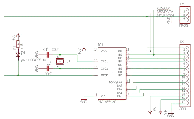
The Eagle Software has two windows namely schematic window and board layout window. The Schematic window, as the name implies is use to draw schematics. Schematic is a drawing which represents the circuit with component symbol and connection lines. In the schematic editor, add all components which is required by your circuit. These components are available in the library. After adding all components in the schematic editor, make a proper connection with wires.
There are two ways to use EAGLE schematic window. One is with graphical icons. It is available in the toolbar (left side of the window). You can interact with these icons by drag and drop with mouse. The second method is with a command line. You can type the command in the command line. For example, if you want to add a component, types ‘add’ in the command line. A new window will open from the library.
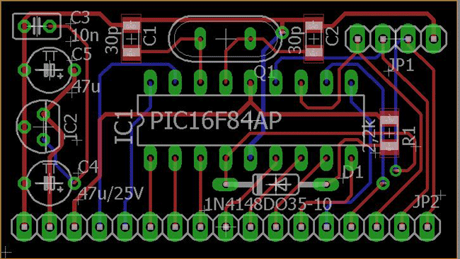
The board layout shows how PCB look like with actual size and place of components. There is a common button  in the schematic window and board layout. This button is used to switch between schematic and board layout windows. Once your board design is complete your board layout would look something like this below.
I believe this has sparked enough interest to start with our tutorial series. In the next part we will learn more about schematics editor and how to use in to create your own schematics on Eagle.

Latest Articles
-

Single-Sided vs. Double-Sided PCBs: Which One Is Right for Your Project?
-

Exploring the Different Types of PCB Layers and its Purpose
-

PCB Connectors: A Comprehensive Guide to the Different Types and Their Applications
-

PCB Soldering Steps
-

Basic Electronic Component Symbols that Every PCB Design Engineer Should Know
-

Home Made PCBs – A Step by Step guide to build PCBs in your Home
Comments